#Upgrading from 3rd/4th Generation to 5th Generation Cortex Barcode Scanner
This is for upgrading from 3rd/4th Generation to 5th Generation. Typically this is beneficial as 4th Generation tends to have high amounts of issues during kiosk restarts, which tends to relieve long term issues.
- Disconnect the USB Cable and Cable
J7on theDVD-36-000-04Gripper Board - Loosen 2 Bolts Holding the old Camera Device
- Grab the
Cortex Barcode Scannerand mount to the bracket. - Install the Cortex Barcode Scannner using the same 2 bolts holding the old mount
- Install the 5th Generation Camera from the Redbox Technician Driver Kit.
If you are using Windows 11, you will need to use the CR1100 drivers from CodeCorp's Website, which also support CR1000 devices.
- Modify
hal.xmland apply the following to the camera properties:
  <Camera>
   <CameraPlugin>DirectShowFrame</CameraPlugin>
   <SnapDecodePort>COM6</SnapDecodePort>
   <WritePause>500</WritePause>
   <RebootOnStart>true</RebootOnStart>
   <EnableInfared>false</EnableInfared>
   <CycleCameraOnUse>False</CycleCameraOnUse>
   <UseInliteOnFail>True</UseInliteOnFail>
   <ScannerService>Cortex</ScannerService>
   <LogDetailedScan>False</LogDetailedScan>
   <InsertReadStats>true</InsertReadStats>
   <ExpectedCodes>4</ExpectedCodes>
   <ScanTimeout>2000</ScanTimeout>
   <ScannerWakeupPause>15000</ScannerWakeupPause>
   <FilterExcessReadCodes>True</FilterExcessReadCodes>
   <CortexPortOpenWait>50</CortexPortOpenWait>
   <CortexSnapOnDecodeFailure>False</CortexSnapOnDecodeFailure>
   <CortexPortBufferSize>8192</CortexPortBufferSize>
   <UseRuntimePath>False</UseRuntimePath>
   <UseCortexHDField>True</UseCortexHDField>
   <IRHardwareInstallDate>NONE</IRHardwareInstallDate>
   <UseInliteForFraudValidation>False</UseInliteForFraudValidation>
   <CortexStartupAction>Decode</CortexStartupAction>
 </Camera>
- Save and close
- Open Command Prompt and execute
reg.exe add "HKLM\SYSTEM\ControlSet001\Services\CCSERMU\Configuration\000000000000" /v PortName /t REG_SZ /d "COM6" /f - Restart the computer
If done correctly, your Cortex Barcode Scanner Should work as expected. If you are getting a scanning error, Double check the steps above were followed correctly.
#From HardDrive to a Solid-State Drive
For this, we will be using Macrium Reflect 8 (X works the same, but it is trialware and only restoring works after the trial period) though there are other tools to clone to a drive. You will need to prep the PC.
#Pre-existing OS Cloning/Restoring
This is for cloning your previous OS from your physical drive.
- Disconnect the HardDrive from the Kiosk PC
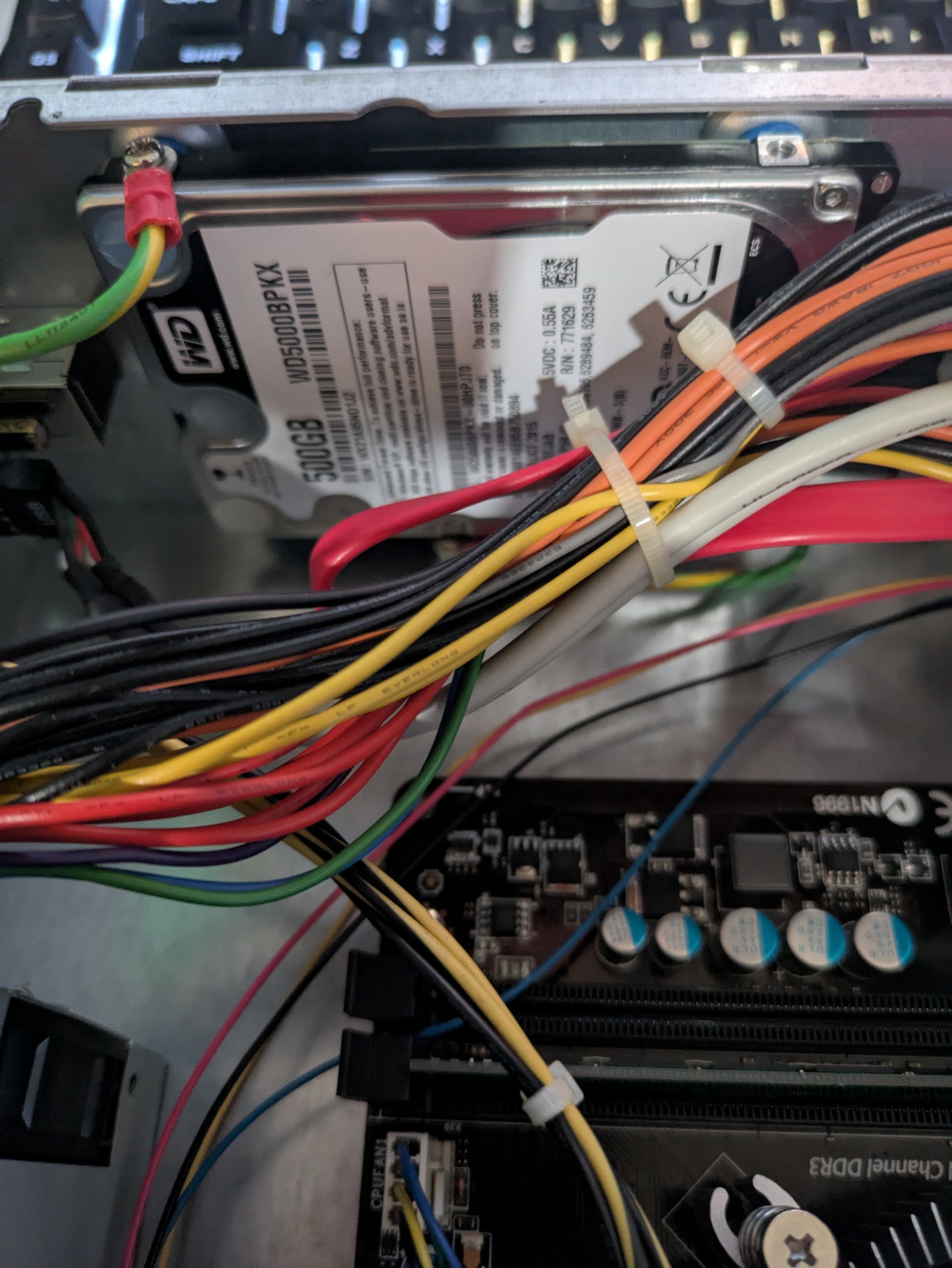
- Plug the Harddrive and Solid-State Drive into your PC (Recommended) or a SATA Drive Dock.
- Open Macrium Reflect.
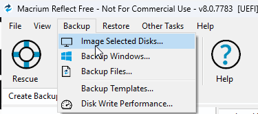
- Locate Backup and select Image Selected Disks.
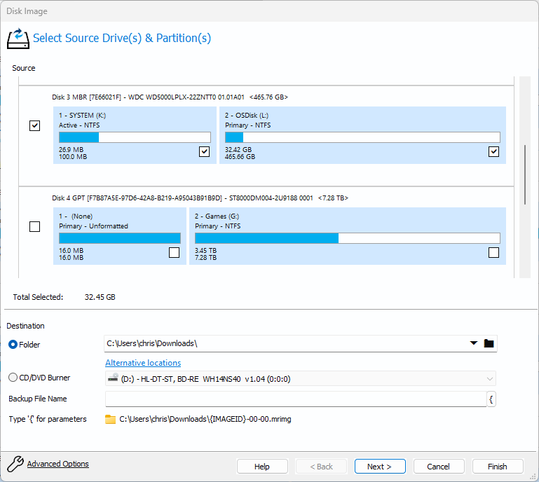
- Select the drive you wish to back up and restore on a Solid-State Drive.
- You can skip the Edit the Plan for this Backup window as this is not required for our backup
- Check advanced options and make sure the Compression Level is set to Medium and use Intellegent sector copy.
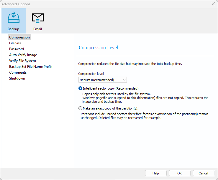
If your backup fails upon restoring, you can set Compression Level to None which sometimes solves this issues.
- Press Finish and your backup should start. We recommend using Macrium Reflect 8 at the Highest Priority to speed up the backup process.
- Once Finished, you will need to navigate to Restore and look for Browse for an image or backup to restore... and select the image we just backed up.
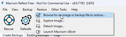
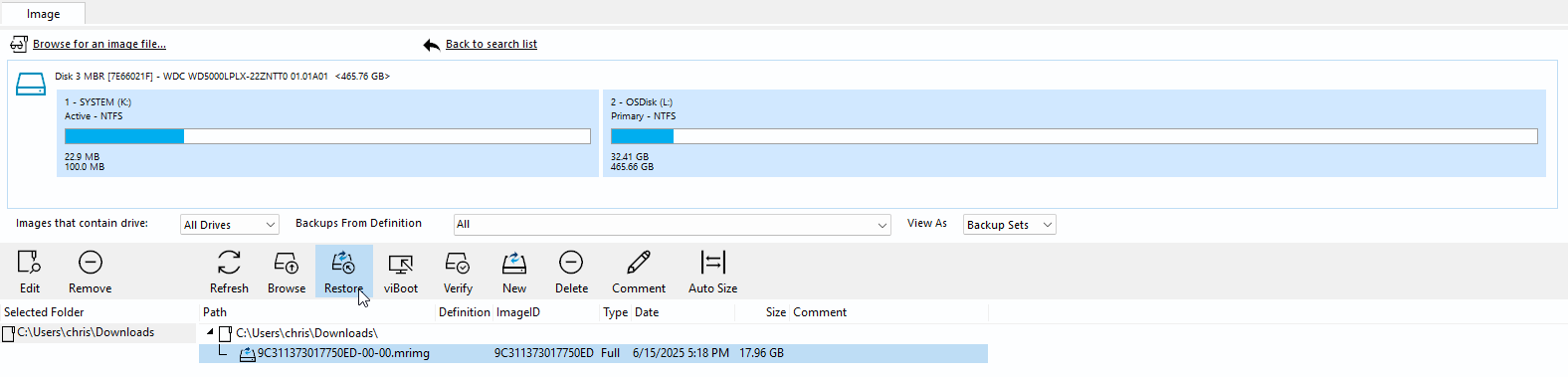
- Press Restore once you verify the contents match what we backed up earlier.
- Make sure you select the correct target disk, then select Erase Disk and Copy Partitions.
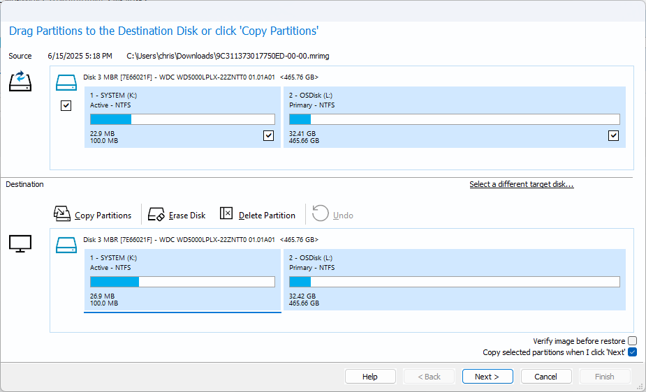
- Press Finish and Macrium should start restoring.
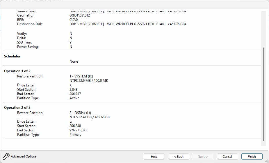
- Unplug the Solid-State Drive from your PC or Dock and Plug it back into your Kiosk PC.
- Boot up the PC and verify it boots properly before plugging all the cables back into your kiosk and screwing the Solid-State Drive to the mount in the case.
#Restoring from Images
Wanting to upgrade to the Windows 10 Image or having to get the Windows 7 Image because the drive was dead on arrival or missing? This section should help with restoring. You will need to get the images from the discord server.
- Plug the Harddrive (7200 RPM Recommended. 5400 RPM will have a hard time querying the VistaDB database and may crash the kiosk software) or Solid-State Drive (Recommended) into your PC (Recommended) or a SATA Drive Dock.
- Open Macrium Reflect.
- Navigate to Restore and look for Browse for an image or backup to restore... and select the image we downloaded from the discord server.
- Press Restore.
- Make sure you select the correct target disk, then select Erase Disk and Copy Partitions.
- Press Finish and Macrium should start restoring.
- Unplug the drive from your PC or Dock and Plug it back into your Kiosk PC.
- Boot up the PC and verify it boots properly before plugging all the cables back into your kiosk and screwing the Solid-State Drive to the mount in the case.
If you start experiencing issues, you may need to repeat all steps again after re-downloading the image. Also follow Migrate from old kiosk to new kiosk guide to get your kiosk running with settings from your old kiosk.
#Re-wiring your Kiosk (Outdoor Only)
Electrical work must be performed with extreme caution and precision. If you are unsure about any part of this process, or lack the proper tools or experience, stop immediately and consult a licensed electrician. Improper wiring can result in serious injury, death, fire, and/or damage to kiosk equipment.
This guide is for individuals who plan to reuse the existing outlets within the kiosk. If you're not confident in completing this process, consider using an extension cord as an alternative. Make sure the cord supports at least 125V. Keep in mind that, depending on the type of cord used, it may obstruct the removal and reinstallation of the drop bin.
#Required Tools & Materials
- 1x 12-AWG/2 or 12AWG/3 Power Cord (25ft)
A thick, durable cable suitable for 20-amp circuits. The 25ft length should give you plenty of wire to work with inside the kiosk. You technically shouldn’t need more than 15 feet, but this allows you to have the proper lengths for daisy chaining from Outlet 1 to Outlet 2 - 1x GFCI Outlet Tester
Use this to verify that the outlet is properly wired and the GFCI protection works as intended. - 1x 3/8" Clamp-on Service Entrance Connector
Prevents stress or accidental tugging from damaging the internal wiring. Required for secure and safe cable entry into the box. - 5x 12-10 Yellow Ring Terminals
These will be crimped onto the ground wires to ensure a tight, secure, and corrosion-resistant connection to the outlets and chassis. - 1x Wire Stripper/Cutter/Crimper Tool
A basic model will do fine. Used to cut wire to length, strip the outer jacket, and crimp terminals to the exposed copper. - 1x GFCI Outlet or 1x 20 Amp Circuit Breaker
Even though you're using 12 AWG wiring rated for 20 amps, GFCI outlets usually max out at 15 amps. Do not exceed the rated amperage.
For permanent or outdoor setups, you may want to install a dedicated 20-amp breaker. If you’re not experienced with electrical panels, hire a licensed electrician to handle this part.
- 1x 1/2" Plastic Screw-in Connector Conduit Fitting
Optional, but great for helping keep moisture and rain out of the box, especially if the kiosk is outdoors.
#Optional Parts
- 2x 20-Amp 125V Outlets (or better)
Used if you're replacing both receptacles inside the kiosk. - 1x 1/2" Plastic Screw-in Connector Conduit Fitting
Great for helping keep moisture and rain out of the box, especially if the kiosk is outdoors. Most of the time, it is ok to re-use the old one, but is a good idea to use a new one to keep water from entering the kiosk.
#Replacement Steps
Disassemble the Electrical Box
- Unscrew and remove the two bolts holding the electrical box in place inside the kiosk.
- Pull the box outward carefully to access the internal wiring.
Remove the Old Wiring
- Disconnect and discard all old wiring inside the box.
- You may need to cut the old green ground wire connected to the kiosk body. Don’t worry—you’ll replace it with fresh wire.
Inspect the Kiosk Entry Point
- Check the condition of the plastic screw-in fitting where the cable enters the kiosk.
- If damaged or missing, replace it to ensure weather resistance.
Feed in the New Power Cord
- Insert your 12 AWG power cord through the back of the kiosk and into the box area.
- Pull enough slack through to work comfortably and reach all terminals.
Strip the Outer Jacket
- Use a wire stripper to remove the outer black insulation from the cord—be careful not to nick the internal wires.
- You should see three wires inside:
- Black or Red = Hot/Live
- White = Neutral
- Green = Ground
Replace the Clamp Connector
- Remove the existing 3/8″ clamp connector from the electrical box.
- Install the new clamp connector and feed the stripped cable through it.
- Tighten the clamp securely to prevent movement.
Prepare the Jumper Wire
- Cut a short length of cable to connect the first outlet to the second outlet inside the box.
- Leave extra length in case you ever need to remove or reposition the outlets.
Strip and Prep Wires
- Strip both ends of the jumper wire: remove the jacket and expose the individual conductors.
- Crimp a yellow ring terminal onto the ground wire at both ends.
Secure Cable and Connector
- Insert the power cord and jumper wire into the electrical box.
- Tighten the clamp-on connector to hold everything in place.
Tie the Underwriter’s Knot
- Before connecting to the GFCI or breaker:
- Create a loop in the hot and neutral wires.
- Intertwine them so they form a knot (prevents tension on the terminals).
- Pull the knot tight and push it back into the box.
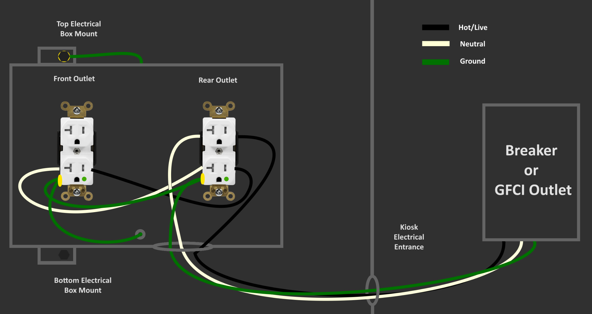
Connect to Outlet 1
- Using the labeling on the outlet, connect:
- Black/Red (Live) to the brass screw
- White (Neutral) to the silver screw
- Green (Ground) (ring terminal) to the green screw
Connect the Jumper to Outlet 2
- Repeat the connections using the jumper wire on Outlet 2:
- Live to brass screw
- Neutral to silver screw
- Ground (ring terminal) to green screw
Install and Mount the Outlets
- Secure Outlet 1 (the back outlet) to the electrical box.
- Tighten the mounting screws and install the cover plate.
Ground to Kiosk Frame
- Cut another length of ground wire to run from Outlet 2 to the metal frame of the kiosk.
- Crimp ring terminals on both ends.
- Secure one end to the green screw on Outlet 2 and the other to the chassis ground point on the kiosk.
Final Assembly
- Neatly tuck the wires inside the box.
- Reattach the electrical box to the kiosk with the original bolts.
- Ensure everything is tight and sealed.
#Testing and Verification
Ensure all outlet connections are secure and tight before performing any tests. Loose wiring may cause an electrical fire or destroy kiosk equipment.
- Plug in your GFCI Outlet Tester.
- Make sure each outlet shows correct wiring and that GFCI protection functions.
- If you get an error, double-check all wire connections, especially Live vs Neutral.
- Once everything tests correctly, plug in your kiosk equipment.